🧩 VLSM & Practical Network Design
1. What is VLSM?
Variable Length Subnet Mask (VLSM) allows a network to be divided into subnets of different sizes, using different subnet masks for each subnet. This optimizes IP address space usage by allocating exactly the required number of addresses to each subnet, rather than forcing all subnets to be the same size (as in classful or FLSM).
Example: A /24 network (256 addresses) can be subnetted into a /26 (64 addresses) for a small LAN, a /27 (32 addresses) for another, and the remaining addresses used for point‑to‑point links (/30). This avoids wasting addresses.
2. Broadcast Domain (Subnet)
A broadcast domain is a logical division of a network where all devices can reach each other by broadcast at the data link layer. In IP networking, a subnet (or LAN) is a broadcast domain. Routers separate broadcast domains – broadcasts are not forwarded across a router. Therefore, all devices in the same subnet reside in the same broadcast domain until they encounter a router.
3. Practical Network Design Example
We will design a small network using VLSM, document the IP plan, and prepare for implementation in a simulator like Cisco Packet Tracer.
3.1. Topology Description
The network consists of:
- A central router named R-CENTRAL with three Gigabit Ethernet interfaces: G0/0, G0/1, G0/2.
- Three switches: Sw1, Sw2, Sw3.
- Three PCs: PC1, PC2, PC3.
- Three Laptops: Lap1, Lap2, Lap3.
- Three Servers: Srv1, Srv2, Srv3.
Connections:
- LAN1: R-CENTRAL G0/0 → Sw1 Fa0/1; Sw1 Fa0/2 → PC1, Fa0/3 → PC2, Fa0/4 → PC3.
- LAN2: R-CENTRAL G0/1 → Sw2 Fa0/1; Sw2 Fa0/2 → Lap1, Fa0/3 → Lap2, Fa0/4 → Lap3.
- LAN3: R-CENTRAL G0/2 → Sw3 Fa0/1; Sw3 Fa0/2 → Srv1, Fa0/3 → Srv2, Fa0/4 → Srv3.
ASCII Diagram
                         R-CENTRAL
                 +-----------+-----------+
                 | G0/0      | G0/1      | G0/2
                 |           |           |
            +----+----+ +----+----+ +----+----+
            |  Sw1    | |  Sw2    | |  Sw3    |
            +----+----+ +----+----+ +----+----+
                 |           |           |
        +--------+---+  +----+----+  +---+--------+
        |   |   |   |  |   |    |  |  |   |   |   |
       PC1 PC2 PC3    Lap1 Lap2 Lap3  Srv1 Srv2 Srv3
Cisco Packet Tracer screenshot
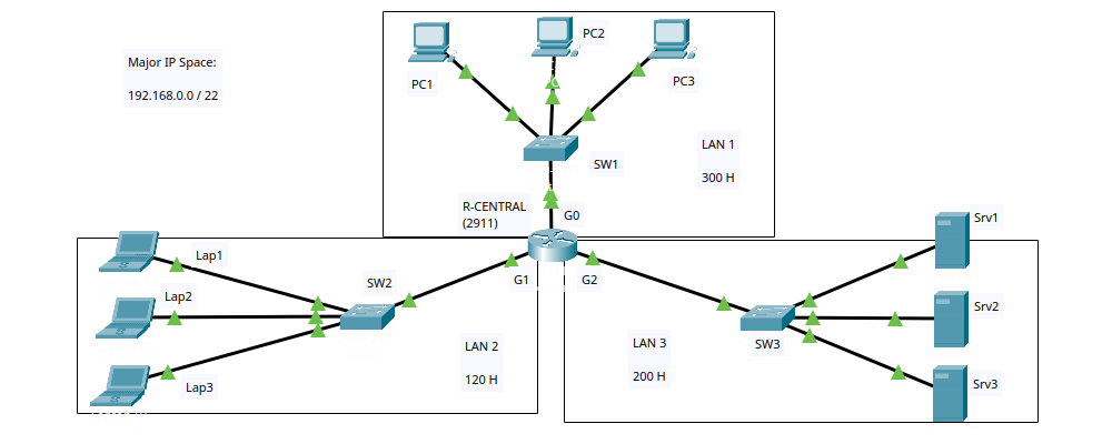
This topology will be built in Packet Tracer and saved as "1 - activity.pkt".
3.2. Host Requirements
We are given the organizational IP space: 192.168.0.0/22.
Host requirements per LAN:
- LAN1 – 300 hosts
- LAN2 – 120 hosts
- LAN3 – 200 hosts
We must subnet this major network into smaller subnets satisfying these requirements.
3.3. Subnetting Table Creation
Step 1: Determine the major network boundaries.
Network address: 192.168.0.0/22 → 192.168.0.0
Broadcast address: 192.168.3.255 (because /22 gives 10 host bits, 210 = 1024 addresses, so 192.168.0.0 – 192.168.3.255).
Step 2: Sort LANs by host requirement (descending).
LAN1 (300) > LAN3 (200) > LAN2 (120). We allocate from the beginning of the range.
LAN1 (300 hosts)
We need a subnet that can accommodate at least 302 addresses (300 hosts + network + broadcast). Find the smallest power of two ≥ 302: 29 = 512. So host bits = 9 → prefix = 32 – 9 = /23.
Starting from 192.168.0.0:
Subnet: 192.168.0.0/23
Network: 192.168.0.0
Broadcast: 192.168.1.255
First usable: 192.168.0.1
Last usable: 192.168.1.254
Mask: 255.255.254.0
LAN3 (200 hosts)
Next available address: 192.168.1.255 + 1 = 192.168.2.0.
Need ≥ 202 addresses. 28 = 256 → host bits = 8 → prefix = /24.
Subnet: 192.168.2.0/24
Network: 192.168.2.0
Broadcast: 192.168.2.255
First usable: 192.168.2.1
Last usable: 192.168.2.254
Mask: 255.255.255.0
LAN2 (120 hosts)
Next available: 192.168.2.255 + 1 = 192.168.3.0.
Need ≥ 122 addresses. 27 = 128 → host bits = 7 → prefix = /25.
Subnet: 192.168.3.0/25
Network: 192.168.3.0
Broadcast: 192.168.3.127
First usable: 192.168.3.1
Last usable: 192.168.3.126
Mask: 255.255.255.128
Step 3: Verify that we fit inside the major network.
Major network: 192.168.0.0/22 (192.168.0.0 – 192.168.3.255)
Last allocated subnet broadcast: 192.168.3.127 ≤ 192.168.3.255 → OK, we fit inside the major network.
3.4. Subnetting Table
| Name | Subnet | Network Address | Broadcast Address | First Usable IP | Last Usable IP | Subnet Mask |
|---|---|---|---|---|---|---|
| LAN1 (300 H) | 192.168.0.0/23 | 192.168.0.0 | 192.168.1.255 | 192.168.0.1 | 192.168.1.254 | 255.255.254.0 |
| LAN3 (200 H) | 192.168.2.0/24 | 192.168.2.0 | 192.168.2.255 | 192.168.2.1 | 192.168.2.254 | 255.255.255.0 |
| LAN2 (120 H) | 192.168.3.0/25 | 192.168.3.0 | 192.168.3.127 | 192.168.3.1 | 192.168.3.126 | 255.255.255.128 |
This table corresponds to the file "2 - Subnetting Table.txt".
3.5. Addressing Table
We assign IPs according to these rules:
- On each router interface, use the first usable IP of the respective subnet. This is not a technical requirements, it is only a custom among network administrators.
- Switches are layer‑2 and are not configured with IPs in this exercise (they remain unaddressed).
- End devices (PCs, laptops, servers) receive consecutive IPs from the pool, starting from the second usable IP. Their default gateway is the router interface IP of that subnet.
| Device | IP Address | Subnet Mask | Default Gateway |
|---|---|---|---|
| R-CENTRAL | |||
| G0/0 | 192.168.0.1 | 255.255.254.0 | — |
| G0/1 | 192.168.3.1 | 255.255.255.128 | — |
| G0/2 | 192.168.2.1 | 255.255.255.0 | — |
| Switches (no IP configuration) | |||
| SW1 | (not configured at this stage) | ||
| SW2 | (not configured at this stage) | ||
| SW3 | (not configured at this stage) | ||
| PCs (LAN1) | |||
| PC1 | 192.168.0.2 | 255.255.254.0 | 192.168.0.1 |
| PC2 | 192.168.0.3 | 255.255.254.0 | 192.168.0.1 |
| PC3 | 192.168.0.4 | 255.255.254.0 | 192.168.0.1 |
| Laptops (LAN2) | |||
| Lap1 | 192.168.3.2 | 255.255.255.128 | 192.168.3.1 |
| Lap2 | 192.168.3.3 | 255.255.255.128 | 192.168.3.1 |
| Lap3 | 192.168.3.4 | 255.255.255.128 | 192.168.3.1 |
| Servers (LAN3) | |||
| Srv1 | 192.168.2.2 | 255.255.255.0 | 192.168.2.1 |
| Srv2 | 192.168.2.3 | 255.255.255.0 | 192.168.2.1 |
| Srv3 | 192.168.2.4 | 255.255.255.0 | 192.168.2.1 |
This table corresponds to the file "3 - Addressing Table.txt".
3.6. Implementation in Packet Tracer
- Build the topology exactly as described and save as "1 - activity.pkt".
- Configure IP addresses on R-CENTRAL's interfaces using the addressing table. Remember to enable the ports (GUI: "Port status: ON" / CLI: "no shutdown" command).
- Configure end devices (PCs, laptops, servers) with their IP, mask, and default gateway. Switches remain unconfigured (default settings are fine).
- Test connectivity with ping:
- Ping from a PC to its gateway (192.168.0.1) – should succeed immediately.
- Ping between devices in different LANs (e.g., PC1 to Srv1) – the first ping may fail due to ARP, but subsequent pings should work. If not, check configurations and use simulation mode to debug.
- All pings should eventually succeed, indicating correct IP assignment and routing (the router automatically routes between its directly connected networks).
Summary
We have successfully:
- Defined VLSM and broadcast domains.
- Designed a multi‑LAN topology with a central router.
- Calculated appropriate subnet sizes based on host requirements using VLSM.
- Documented the subnetting plan and addressing table.
- Prepared for implementation in Packet Tracer with verification steps.
This exercise demonstrates how VLSM efficiently uses IP address space in real‑world network design.